Fabrication article
Industrial Ductwork Fabrication Packages: What the Engineer Should Define Before Release
Define geometry, joints, stiffening, supports, coatings, access, shipping splits, match marks, and inspection before releasing industrial ductwork.
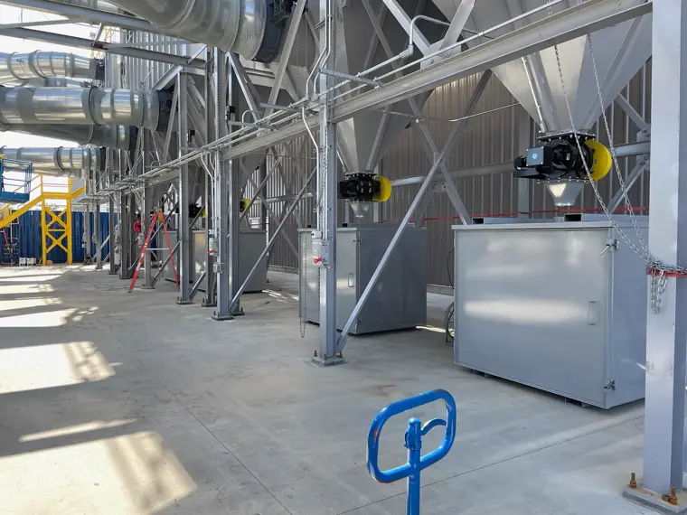
An industrial duct package must translate system design into buildable, shippable sections. The fabricator needs more than centerlines and airflow sizes: material, gauge or thickness, joints, stiffening, supports, access, coating, tolerances, match marking, and shipping boundaries all affect execution.
Short answer: The engineer should define the required system performance and interfaces. The fabrication package should then make every section, joint, support, finish, inspection point, and field connection identifiable before material is cut.
Define service and construction
State the conveyed medium, operating temperature and pressure conditions, corrosion or abrasion concerns, material, thickness, and governing project specification. Identify whether the system is ordinary ventilation, dust collection, process exhaust, or another engineered service.
Do not ask the fabricator to infer design conditions from a plan view.
Break the system into controlled pieces
Assign unique piece marks. Show straight sections, elbows, transitions, branches, access doors, flanges, stiffeners, supports, and field joints. Record the orientation of asymmetric pieces and the relationship to building steel, equipment nozzles, and maintenance access.
Shipping splits should reflect trailer limits, lifting, route access, coating protection, and field assembly—not just convenient drawing boundaries.
Make joints and supports explicit
Define flange or connection type, bolt pattern, gasket responsibility, seal or weld requirement, and field-versus-shop work. Locate stiffeners and supports with enough detail to avoid interference with adjacent equipment or insulation.
If supports are by others, provide the loads and interfaces required by the responsible engineer. If they are included in the fabrication scope, identify them in the BOM and drawings.
Plan finish and handling
Specify surface preparation, coating system, areas left bare for field welding, and touch-up responsibility. Large pieces may need lifting lugs, internal bracing, shipping frames, or protected flange faces. Marking must remain readable after coating and survive shipment.
Confirm before release
Piece marks agree across plans, details, and BOM.
Field joints are accessible and correctly oriented.
Large sections fit the shipping and site route.
Supports, stiffeners, access doors, and insulation clear one another.
Coating and field-weld boundaries are defined.
Pre-assembly, dimensional checks, and leak or weld inspection are stated.
Ahner has fabricated large round and rectangular industrial duct systems. Review related welding and heavy fabrication capabilities or send the current package through the custom quote form.
System design, code selection, and performance requirements remain with the responsible engineer.