Ahner Industrial resource
Stainless Steel Brackets with Cut and Formed Features
Stainless-steel brackets combine elongated cutouts with formed flanges. This Ahner shop example shows why cut geometry, bend placement, and finished.
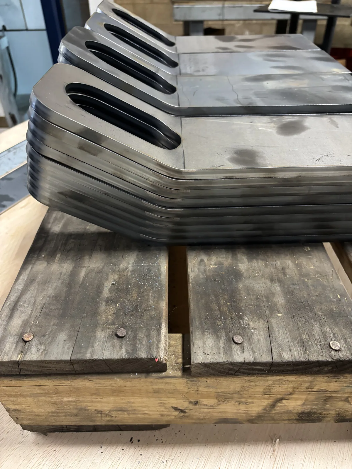
Stainless-steel brackets combine elongated cutouts with formed flanges. This Ahner shop example shows why cut geometry, bend placement, and finished dimensions need to be reviewed together.
Stainless-steel brackets from the Ahner shop, showing elongated cutouts and formed flanges. The photograph shows the parts stacked together during shop handling.
The Documented Scope
Material: Stainless steel
Processes: Profile cutting, Sheet metal forming
Elongated cutouts & formed flanges
The photograph shows matching stainless-steel brackets with cut openings and formed flanges, stacked together in the Ahner shop.
The stainless work shown in the photograph
The pictured parts are stainless-steel brackets. Their elongated openings, cut outlines, and formed flanges are visible in the stack. The photograph brings the two types of geometry into one view: features cut through the material and features created by bending it. The repeated profiles show similar parts grouped together in the shop. This is the fabrication example featured here, with the material identified as stainless steel.
Cut geometry and formed geometry belong to the same part
The openings sit within flanges that change direction from the larger body of each bracket. That relationship makes the finished part more informative than the flat outline alone. When reviewing a similar bracket for manufacturing, Ahner needs to understand where each cut feature belongs after forming, which dimensions control its fit, and which surfaces or edges locate it in the assembly. A flat profile and a finished-part drawing answer different questions and are useful together.
Define stainless requirements before quoting
For a similar stainless component, specify the grade, thickness, required surface condition, and finished geometry. If a face will remain visible in service, identify the cosmetic requirements and any restrictions on tooling marks. Include the bend direction, radius, and dimensions that matter after forming. Those inputs help the shop review cutting, forming, tooling access, and handling for your part. The material specification should come from the drawing or purchase requirements, alongside the geometry.
Use the finished dimensions to guide the fabrication review
An elongated opening and a formed flange may each look straightforward on their own, but their relationship can control how a bracket fits its mating components. For comparable parts, identify the critical opening locations and the flange dimensions in the finished condition. Include the intended quantity and any repeat-order plans when requesting a quote. The stainless brackets shown here offer a clear shop example of cut features and formed geometry in the same component.
Planning a Similar Project
Send both the cut geometry and the finished-part requirements. Identify the stainless grade and thickness, bend directions, critical opening locations, tolerances, and cosmetic surfaces. That gives Ahner a useful starting point for reviewing the part’s cutting, forming, and handling requirements.
What to Send
Send CAD or drawings, stainless grade and thickness, finished dimensions, bend directions and radii, quantity, critical tolerances, surface-finish requirements, and target timing. A photo or sketch can start the discussion when the design is still being defined.